Line Pipe
1. Product Overview
Line pipe refers to steel pipes specifically designed for the transportation of oil, natural gas, water, and other fluids over long distances — from wellhead to processing facilities, storage terminals, and distribution networks. Line pipe is the critical infrastructure component of midstream and downstream oil and gas operations.
Unlike OCTG products, which are subjected to complex downhole loading conditions including tension, compression, collapse, and cyclic fatigue, line pipe is primarily engineered for internal pressure containment and long-term resistance to corrosion, environmental cracking, and external mechanical damage over the service life of a pipeline.
2. Manufacturing Processes
Line pipe is manufactured using three primary processes, each offering distinct advantages for specific applications:
2.1 Seamless Pipe
Process: Produced by piercing and rolling solid steel billets without any longitudinal or spiral welds.
| Features | Applications |
|---|
| Homogeneous structure without weld seam | High-pressure gas transmission |
| Superior reliability in critical locations | Sour service environments |
| Uniform wall thickness | Offshore and deepwater pipelines |
| Limited maximum OD (typically up to 16–20″) | Subsea flowlines |
2.2 Longitudinal Submerged Arc Welded (LSAW) Pipe
Process: Formed from individual steel plates that are pressed or rolled into a cylindrical shape, with the longitudinal seam welded using submerged arc welding (SAW). Typically produced using the UOE (U-ing, O-ing, Expanding) or JCOE (J-ing, C-ing, O-ing, Expanding) forming methods.
| Features | Applications |
|---|
| Excellent dimensional accuracy | Long-distance onshore gas transmission |
| High toughness and strength | Arctic and sub-arctic pipelines |
| Available in large ODs (16″ – 64″) | Deepwater offshore pipelines |
| Superior weld quality due to controlled forming | High-pressure trunk lines |
| Generally more cost-effective than seamless for larger diameters | Sour service and corrosive environments |
2.3 Spiral Submerged Arc Welded (SSAW) Pipe
Process: Formed by spirally winding a steel coil into a cylindrical shape, with the helical seam welded using double-sided submerged arc welding.
| Features | Applications |
|---|
| Wide range of ODs from a single coil width | Water transmission and irrigation systems |
| Cost-effective for thinner walls | Low-pressure gas distribution |
| Good resistance to axial forces | Structural and piling applications |
| Capable of very large ODs (up to 100″+) | Pipeline crossings and river crossings |
| More economical than LSAW for medium and large ODs | Less demanding onshore pipelines |
2.4 Comparison Summary
| Manufacturing Method | Size Range (OD) | Wall Thickness | Typical Cost | Weld Integrity |
|---|
| Seamless | Up to 16–20″ | Up to 30 mm | High | N/A (no seam) |
| LSAW (UOE/JCOE) | 16–64″ | 6.4–40 mm | Medium-High | Excellent |
| SSAW (Spiral) | 8–100″+ | 5.0–25 mm | Low-Medium | Good |
| ERW (Electric Resistance Welded) | Up to 24″ | Up to 20 mm | Low | Good |
3. Full Range of Specifications
3.1 Outside Diameter (OD) Range
| Size Category | OD (mm) | OD (inches) | Typical Applications |
|---|
| Small Diameter | 60.3 – 168.3 | 2 3/8 – 6 5/8 | Gathering lines, flowlines |
| Medium Diameter | 219.1 – 323.9 | 8 5/8 – 12 3/4 | Feeder lines, distribution |
| Large Diameter | 355.6 – 610 | 14 – 24 | Long-distance trunk lines |
| Extra Large Diameter | 711 – 1,422 | 28 – 56 | Major transmission corridors |
| Ultra-large Diameter | 1,524 – 2,540+ | 60 – 100+ | Water transmission, specialized applications |
3.2 Wall Thickness Range
Available wall thicknesses generally range from 5.0 mm to 40.0 mm, with specific combinations depending on OD, steel grade, and design pressure. For heavy-wall applications (deepwater, high-pressure), thicknesses up to 50 mm are achievable.
3.3 Lengths
Line pipe can be supplied in random lengths or specific cut lengths as required by project specifications:
| Length Type | Range | Application |
|---|
| Random Length | 6 – 12 m | General construction |
| Specified Length | 6 – 18 m (or as ordered) | Project-specific requirements |
| Double Random | 18 – 24 m | Reducing number of field welds |
| Ultra-long Lengths | Up to 36 m | Offshore reel-lay installations |
4. Applicable Standards
4.1 International Standards
| Standard | Description |
|---|
| API 5L (46th Edition) | Line Pipe – the primary global standard covering seamless and welded steel pipe for pipeline transportation systems |
| ISO 3183 | Petroleum and natural gas industries – Steel pipe for pipeline transportation systems (aligned with API 5L) |
| API 5LD | Specification for CRA Clad or Lined Steel Pipe (corrosion-resistant alloy clad pipe) |
| API 5LW | Line pipe transported by barge or vessel |
| ASME B31.4 | Pipeline transportation systems for liquid hydrocarbons and other liquids |
| ASME B31.8 | Gas transmission and distribution piping systems |
| DNVGL-ST-F101 | Submarine pipeline systems (offshore pipelines) |
| BS 8010 | Code of practice for pipelines (UK standard) |
| NACE MR0175 / ISO 15156 | Materials for use in H₂S-containing environments |
4.2 Chinese National Standards
| Standard | Description |
|---|
| GB/T 9711 | Petroleum and natural gas industries – Steel pipe for pipeline transportation systems (equivalent to API 5L) |
| SY/T 5037 | Spiral submerged-arc welded steel pipe for pipelines |
| SY/T 5040 | Longitudinal submerged-arc welded steel pipe for pipelines |
| GB/T 3091 | Welded steel pipe for low-pressure liquid delivery |
5. Steel Grades
5.1 API 5L Steel Grades
All API 5L steel grades are available with Product Specification Levels (PSL-1 and PSL-2). PSL-2 offers stricter chemical, mechanical, and testing requirements for more demanding applications.
| Grade | Minimum Yield Strength (MPa) | Minimum Yield Strength (ksi) | Typical Application |
|---|
| A25 | 172 | 25 | Low-pressure distribution |
| A | 207 | 30 | Low-pressure distribution |
| B | 241 | 35 | General onshore pipelines |
| X42 | 290 | 42 | Standard transmission lines |
| X46 | 317 | 46 | Medium-pressure pipelines |
| X52 | 359 | 52 | Widely used for oil and gas transmission |
| X56 | 386 | 56 | Higher pressure transmission |
| X60 | 414 | 60 | High-pressure transmission |
| X65 | 448 | 65 | High-pressure transmission, offshore |
| X70 | 483 | 70 | Long-distance high-pressure gas lines |
| X80 | 552 | 80 | High-strength large-diameter pipelines |
| X90 | 621 | 90 | High-strength specialized applications |
| X100 | 690 | 100 | Ultra-high strength, deepwater and HPHT |
Note: Grades X90 and X100 are not covered as PSL-2 grades in API 5L and require supplementary specifications.
5.2 Special Service Steel Grades
Beyond standard API grades, line pipe is available with enhanced properties for specific service conditions:
5.2.1 Sour Service (H₂S Resistance)
| Grade Designation | Description |
|---|
| API 5L PSL-2 Sour Service | Grades with "S" suffix (e.g., X60S, X65S, X70S) – engineered for H₂S-containing environments |
| Severe Sour Service | Proprietary grades with hardness limitation (typically ≤250 HV10), grain size control (ASTM 6–8), and rigorous SSC and HIC testing per NACE TM0284 and NACE TM0177 |
5.2.2 Offshore and Submarine Service
| Grade Designation | Description |
|---|
| API 5L PSL-2 Offshore | Enhanced toughness at low temperatures (typically –10°C to –46°C), Charpy V-notch testing |
| DNV SAW / SML Grades | DNVGL-ST-F101 grades (e.g., SAW 450, SML 450) with stringent impact, CTOD, and DWTT requirements |
| Subsea Flowline Grades | Heavy-wall with superior weld CTOD toughness for reel-lay and dynamic riser applications |
5.2.3 Low-Temperature Service
| Grade Designation | Description |
|---|
| Low-Temperature Grades | X52LT, X65LT, X70LT – optimized for arctic and sub-arctic conditions with impact testing at –40°C to –60°C |
| CTOD Grades | Crack Tip Opening Displacement tested for fracture mechanics at low temperatures |
| DWTT Grades | Drop Weight Tear Test requirements to ensure ductile fracture behavior in cold environments |
5.2.4 High-Temperature / HPHT Service
| Grade Designation | Description |
|---|
| Creep-Resistant Grades | Proprietary chemistry and heat treatment for elevated temperature (up to 350°C) |
| CRA Clad/Lined Pipe | API 5LD – metallurgically bonded or mechanically lined with corrosion-resistant alloys (stainless steel, nickel alloys) for extreme HPHT + corrosive conditions |
6. Coatings and Linings
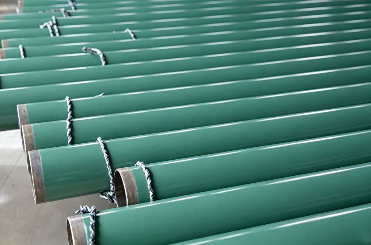
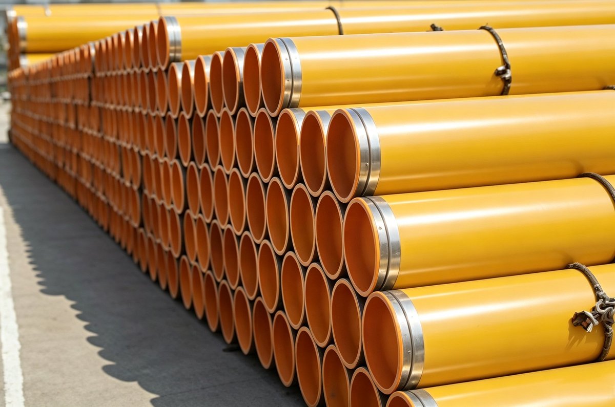
Line pipes are protected with various external and internal coating systems to prevent corrosion, reduce friction, and extend service life.
6.1 External Coatings
| Coating Type | Description | Applications |
|---|
| Shop Primer / Rust Preventive Varnish | Thin temporary coating (10–30 µm) for protection during storage and transport | Standard, short-term storage |
| Fusion Bonded Epoxy (FBE) – Single Layer | Thermosetting epoxy powder applied at high temperature (200–250°C), typically 250–500 µm | General corrosion protection, onshore pipelines |
| FBE – Dual Layer (Dual FBE) | Two FBE layers applied in sequence (typically 500–800 µm total) | Enhanced mechanical and corrosion resistance |
| 3LPE (Three-Layer Polyethylene) | Epoxy primer + copolymer adhesive + extruded polyethylene (1.5–3.5 mm) | Onshore pipelines, high abrasion resistance |
| 3LPP (Three-Layer Polypropylene) | Epoxy primer + copolymer adhesive + extruded polypropylene (2.0–4.0 mm) | Offshore pipelines, high-temperature service, superior mechanical protection |
| Concrete Weight Coating (CWC) | Reinforced concrete layer (40–120 mm) applied over FBE or 3LPE | Offshore subsea pipelines – provides negative buoyancy and mechanical protection |
| Thermal Spray Aluminum (TSA) | Aluminum coating applied by arc spraying | Offshore and marine environments, cathodic protection |
6.2 Internal Coatings
| Coating Type | Description | Applications |
|---|
| Internal FBE | Epoxy powder coating (250–500 µm) applied to the internal surface | Corrosion protection, gas transmission |
| Internal Flow Coat | Smooth epoxy or polyurethane coating for friction reduction | Liquid pipelines, enhanced flow efficiency |
| Cement Mortar Lining | Thick cement lining applied centrifugally | Water pipelines, corrosion protection |
| CRA Clad / Lined Pipe | Metallurgically bonded stainless steel or nickel alloy layer (2–3 mm) | Severe sour, sweet, and HPHT service |
| Glass Flake Epoxy | Epoxy reinforced with glass flakes (1,000–2,000 µm) | Aggressive chemical and high-temperature service |
6.3 Coating Selection Guide
| Service Environment | Recommended External Coating | Recommended Internal Coating |
|---|
| Onshore – Moderate | FBE or 3LPE | Internal FBE or plain |
| Onshore – Aggressive Soil | 3LPE | Internal FBE |
| Offshore – Subsea | 3LPP + CWC (as required) | Internal FBE or CRA lined |
| Offshore – Riser | 3LPP (high mechanical) | CRA clad or internal FBE |
| Sour Service | FBE or 3LPE | Internal FBE |
| High Temperature | 3LPP | CRA lined or glass flake epoxy |
| Water Pipelines | FBE or 3LPE | Cement mortar lining |
7. End Finishes
Line pipe can be supplied with various end treatments depending on the joining method and field welding requirements.
7.1 Plain End (PE)
| Description | Features |
|---|
| Pipe ends are cut square | Simple, cost-effective |
| No bevel or threading | For field welding with standard butt-weld preparations |
| Flat/square cut | Welding preparation performed in the field |
7.2 Beveled End (BE)
| Description | Features |
|---|
| Pipe ends are machined with a beveled edge | J-preparation (30°–37.5°) with root face |
| Provides proper groove geometry for welding | Reduced field welding time |
| Typically with an included angle of 60°–75° | Standard for most line pipe applications |
| Bevel Type | Description |
|---|
| V-Bevel | Single V-groove for wall thickness up to 15 mm |
| Double V-Bevel (X-Bevel) | Double-sided preparation for thick walls (>15 mm) |
| Compound Bevel (J-Bevel) | J-groove preparation with curved root |
| K-Bevel | Asymmetric bevel for restricted access welds |
7.3 Threaded End (with Threading)
| Description | Applications |
|---|
| Pipe ends machined with API threads (usually API 5B line pipe threads) | Small-diameter gathering lines and distribution systems |
| Standard coupling connections (NUE or EUE) | Low-pressure applications |
| Thread protectors supplied on both ends | Temporary piping and pump station connections |
7.4 Special End Finishes
| Finish | Description |
|---|
| Belled Ends | Expanded pipe ends for bell-and-spigot joints (cast iron style) |
| Grooved Ends | Machined grooves for mechanical couplings (Victaulic-type) |
| Flanged Ends | Forged or welded flanges bolted to piping systems |